Top 5 Worst Transmission Line Disasters in History
Causes, technical failures, cascading effects, and engineering lessons learned
This article focuses on the largest, most disruptive, and most studied failures involving overhead transmission lines—due to storms, ice, fire, earthquakes, design flaws, and systemic weaknesses.
If you want the Blogger-ready HTML, tell me after reading.
🌩️ TOP 5 WORST TRANSMISSION LINE DISASTERS IN HISTORY
⚠️ 1. North American Northeast Blackout – 2003 (USA & Canada)
Impact: 55 million people affected
Cause: Transmission line contact with trees + grid instability
Region: Ohio, Michigan, Ontario, New York
Duration: 2–4 days (some areas 1 week)
Outage Size: 61,800 MW lost
The 2003 blackout is the most studied transmission-related disaster in history.
Root Transmission-Line Failures
-
A 345 kV line sagged into overgrown trees due to inadequate vegetation management.
-
Three more lines tripped sequentially under overload.
-
Operators were unaware because the alarm server at FirstEnergy failed silently.
Technical Failure Chain
-
Excessive conductor temperature → sag → vegetation contact
-
Protection relays tripped the lines
-
Power rerouted → overload on adjacent lines
-
Voltage collapse across the Great Lakes region
-
Cascading outages across 8 U.S. states + Ontario
Key Engineering Lessons
-
Vegetation management must be treated as a critical protection function.
-
SCADA alarms require redundancy.
-
High-voltage AC grid must use adaptive islanding to avoid cascade.
-
Dynamic line rating (DLR) can prevent overheating.
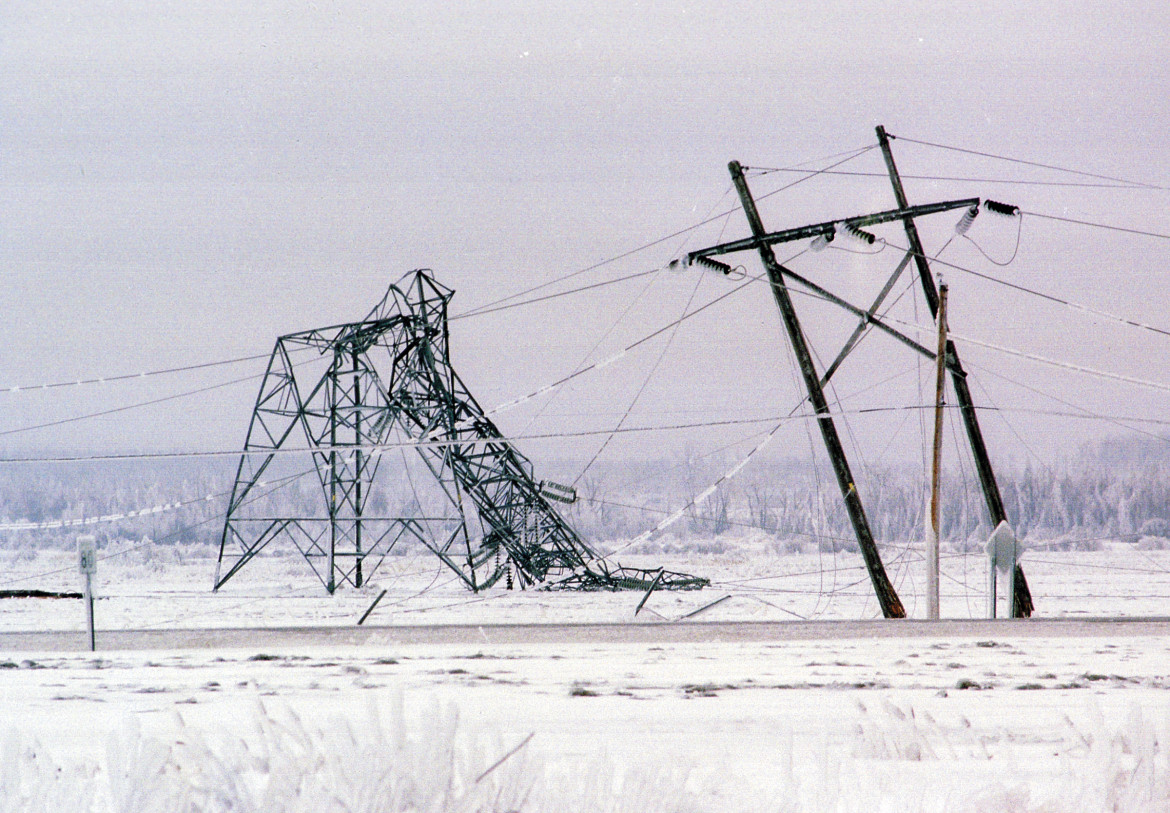
⚠️ 2. Québec Ice Storm Transmission Collapse – 1998 (Canada)
Impact: Entire Montréal region blacked out
Damage: 130+ transmission towers collapsed
Voltage Levels: 735 kV, 315 kV
Duration: Up to 3 weeks for some locations
Cause: Once-in-a-century super-icing storm
This was one of the worst physical failures of overhead lines ever recorded.
What Failed
-
Ice accretion exceeded 80–110 mm radial thickness.
-
Tower loads exceeded design by >250%.
-
Entire 735 kV lines collapsed like dominoes.
-
Multiple lines failed simultaneously → no redundancy.
Lessons Learned
-
Icing design standards changed globally after 1998.
-
Anti-icing conductor designs were adopted.
-
Bundled conductors are now designed for galloping under ice load.
-
Some utilities now use de-icing stations on 735 kV lines.
⚠️ 3. India Northern Grid Collapse – 2012 (World’s Largest Blackout)
Impact: 620 million people without power
Cause: Transmission overload + weak interregional ties
Region: North, East, Northeast India
Voltage Levels: 400 kV, 765 kV AC
Duration: 2 days
Trigger Event
-
Overdrawing by states overloaded key 400 kV corridors.
-
A 400 kV line tripped, pushing flow to parallel lines → overload → cascading failures.
-
Frequency fell to 47.6 Hz, causing collapse.
Physical Line Failures
-
Tower oscillations under heavy loading
-
Relay miscoordination
-
Series compensation instability
Lessons Learned
-
Strict load dispatch compliance
-
FACTS devices (STATCOMs, SVCs) for voltage stability
-
Underfrequency and undervoltage load-shedding automation
⚠️ 4. Chile 500 kV Earthquake Transmission Failure – 2010
Impact: 80% of Chile lost power
Cause: 8.8 magnitude earthquake + tower collapse
Transmission Level: 500 kV AC backbone
Region: Maule, Bio-Bío, Santiago
What Happened
-
Tower foundations failed due to soil liquefaction.
-
Several 500 kV towers collapsed.
-
Substations suffered mechanical damage.
-
Protective relays misinterpreted earthquake-related oscillations.
Engineering Failures
-
Older towers lacked seismic reinforcement.
-
Soil liquefaction was not reflected in vintage foundation designs.
-
Grid islanding was not fast enough.
Post-Event Engineering Innovations
-
Seismic-resistant tower bases
-
Deep micro-pile foundations
-
Earthquake-triggered controlled islanding systems
⚠️ 5. Brazil Rio Madeira 500 kV Corridor Collapse – 2014 (Windstorm + Design Flaw)
Impact: 250+ towers damaged
Cause: Extreme windstorm + structural weakness
Voltage: 500 kV AC
Region: Rondônia & Acre (Amazon)
Duration: Weeks to restore
Cause Breakdown
-
Amazon windstorm surpassed 150 km/h.
-
Towers failed due to:
-
weak bracing in older designs
-
insufficient wind load assumptions
-
poor soil anchoring in wetlands
-
Lessons Learned
-
Wind load maps in tropical storm zones must be updated.
-
Monsoon-grade anti-galloping spacers are required.
-
Modern tower designs use:
-
Corten weathering steel
-
wider crossarms
-
stronger X-bracing
-
⚠️ OTHER NOTABLE DISASTERS (brief)
🔹 Ukraine Power Grid Attacks (2015–2022)
-
Transmission towers destroyed by warfare
-
Required rapid emergency rebuild strategies
🔹 Texas Winter Storm (2021)
-
345 kV grid derated due to icing + gas plant failures
-
Not as many towers collapsed, but systemwide collapse occurred
🔹 China Ice Storm (2008)
-
1,500 towers damaged
-
Led to new anti-icing standards in China
⚙️ TOP ENGINEERING LESSONS ACROSS ALL DISASTERS
1. Vegetation Management = Protection Layer
-
Tree contact is the #1 cause of AC line faults worldwide.
-
Needs predictive thermal sag modeling.
2. Ice Loading Must Be Conservatively Designed
-
Ice storms cause more physical failures than hurricanes.
-
Anti-icing conductors and aerodynamic spacers essential.
3. Wide-Area Protection Systems Are Critical
Modern grids require:
-
synchrophasors (PMUs)
-
adaptive relays
-
traveling-wave fault locators
-
dynamic islanding
4. Redundancy Must Be Built into Transmission Corridors
Parallel lines reduce the risk of cascading outages.
5. Climate Models Must Be Updated
Old wind/ice maps are no longer valid due to:
-
climate change
-
new storm patterns
-
extreme weather intensification