Overall ratings
The overall ratings of PMFSG shall include the following:
a) Rated power frequency;
b) Rated maximum voltage;
c) Rated lightning-impulse withstand voltage;
d) Rated power-frequency withstand voltage;
e) Rated short-circuit current.
Rated power frequencyThe rated power frequency shall be the frequency at which the PMFSG and its components are designed to operate. The preferred rated power frequency is 50 Hz or 60 Hz.
Rated maximum voltage
The rated maximum voltage of PMFSG shall be that of the way with the lowest rating. A three-phase PMFSG containing one or more ways with components, such as fuses, single-phase switches, or fused-loadbreak devices rated for phase-to-ground voltage (maximum voltage divided by 1.732), shall have the designation “Grd-Y” (grounded-wye) added to the rated maximum voltage.
The application of Grd-Y rated PMFSG should be limited to those three-phase applications where the recovery voltage, during switching or fault clearing across any Grd-Y rated way, does not exceed the phase-to-ground rating of components, and the three-phase system voltage does not exceed the rated maximum voltage of the PMFSG.
Rated lightning-impulse withstand voltage
The rated lightning-impulse withstand voltage shall be that of the way with the lowest rating.
Rated power-frequency withstand voltage
The rated power-frequency withstand voltage shall be that of the way with the lowest rating.
Rated short-circuit current
The rated short-circuit current shall be the lowest of the following ratings of any of the ways, and shall be expressed in both symmetrical (sym) and asymmetrical (asym) rms amperes (peak amperes may also be included or substituted for asymmetrical amperes):
a) The rated interrupting current of the fuses, if applicable (see IEEE Std C37.41-1994);
b) The rated momentary and short-time current of the switches, loadbreak devices (if applicable), and bus;
c) The rated fault-closing current of the switches and loadbreak devices.
NOTES
1—A PMFSG consisting of only a single switched way and ways containing fuses may have a rated short-circuit current equal to that of the fuses, if it can be demonstrated that the switch can withstand the fault-closing and momentary duty, as limited by the fuses.
2—Bushings, separable connectors, terminators, or cables may not have short-circuit capabilities as high as the rating of the gear, and could limit the application.
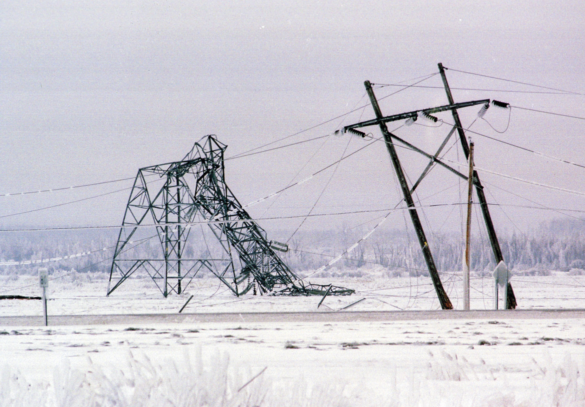
Top 5 Worst Transmission Line Disasters in History
Top 5 Worst Transmission Line Disasters in History Causes, technical failures, cascading effects, and engineering lessons learned This a...
-
Hello. In this blog, we will try to create a steel pole model, using the PLS Pole software of Power Lines System. This created pole will pr...
-
 When a conductor is covered with ice and/or is exposed to wind, the effective conductor weight per unit length increases. During occasions o...
 -
Transmission Line Sag & Tension: Complete Engineering Guide (IEC 60826 / ASCE 74 / PLS-CADD) A full technical guide on sag–tension engi...
