The main protection system for a given zone of protection is called the primary protection system. It operates in the fastest time possible and removes the least amount of equipment from service.
On Extra High Voltage (EHV) systems, i.e., 345kV and above, it is common to use duplicate primary protection systems in case a component in one primary protection chain fails to operate.
This duplication is therefore intended to cover the failure of the relays themselves. One may use relays from a different manufacturer, or relays based on a different principle of operation to avoid common-mode failures.
The operating time and the tripping logic of both the primary and its duplicate system are the same. It is not always practical to duplicate every element of the protection chain.
On High Voltage (HV) and EHV systems, the costs of transducers and circuit breakers are very expensive and the cost of duplicate equipment may not be justified. On lower voltage systems, even the relays themselves may not be duplicated.
In such situations, a backup set of relays will be used. Backup relays are slower than the primary relays and may remove more of the system elements than is necessary to clear the fault.
Remote Backup
These relays are located in a separate location and are completely independent of the relays, transducers, batteries, and circuit breakers that they are backing up. There are no common failures that can affect both sets of relays.
However, complex system configurations may significantly affect the ability of a remote relay to ‘‘see’’ all faults for which backup is desired. In addition, remote backup may remove more sources of the system than can be allowed.
Local Backup
These relays do not suffer from the same difficulties as remote backup, but they are installed in the same substation and use some of the same elements as the primary protection. They may then fail to operate for the same reasons as the primary protection.
CROSSARMS USED IN TRANSMISSION LINES BASIC AND TUTORIALS
Cross arms are now almost limited to carrying polyphase circuits in areas where appearance is not of paramount importance. They are also used where lines cross each other or make abrupt turns at large angles to each other.
They are used as alley or side arms in which the greater part of their length extends on one side of the pole to provide adequate clearances where pole locations may be affected by limited-space rightsof- way. Cross arms are shown in Figure below.

Uses of cross arms: (a) line arm; (b) side arm; (c) buck arm; (d) double arms.
Loadings
The cross arm acts as a beam, supported at the point of attachment to the pole, and must be capable of being subjected to vertical loadings from the weight of the conductors (encased in ice) and a 225-lb worker (specified as an additional safety measure).
It is also subjected to horizontal loadings stemming from winds and from tension in the conductors where the tensions on each side of the pole do not cancel each other; e.g., where spans or conductors are not the same on each side of the pole, at dead ends, bends, or offsets in the line, or where consideration is given to conductor breaking contingencies.
Stresses
The same principles for determining stresses in beams as were applied in the case of poles may also be applied to cross arms; see Figure below.

Bending Moment
The total bending moment M is equal to the sum of all the individual loads multiplied by their distances from the cross section under consideration. Ordinarily, the weakest section should be at the middle of the arm where it is attached to the pole.
At the pin holes, however, the cross section of the cross arm is reduced and may, under unusual circumstances, be the weakest point in the cross arm. The determination can easily be made by computing unit fiber stress at the several points.
Like the pole, the cross arm acts as a beam and the same formula for determining stresses may be employed:
f = M/ lie
where f = maximum unit fiber stress occurring at extreme edges of cross section, lb/in2
M = total bending moment, in•lb
I = moment of inertia of cross section
e = distance from neutral axis to extreme edge, in
The moment of inertia for a rectangular cross section is
I = 1/12 x bd3 and c = d/2
so that the section modulus
I/c = 1/6 x db3
where the neutral axis is parallel to side d, as shown in Figure below
 .
.
They are used as alley or side arms in which the greater part of their length extends on one side of the pole to provide adequate clearances where pole locations may be affected by limited-space rightsof- way. Cross arms are shown in Figure below.

Uses of cross arms: (a) line arm; (b) side arm; (c) buck arm; (d) double arms.
Loadings
The cross arm acts as a beam, supported at the point of attachment to the pole, and must be capable of being subjected to vertical loadings from the weight of the conductors (encased in ice) and a 225-lb worker (specified as an additional safety measure).
It is also subjected to horizontal loadings stemming from winds and from tension in the conductors where the tensions on each side of the pole do not cancel each other; e.g., where spans or conductors are not the same on each side of the pole, at dead ends, bends, or offsets in the line, or where consideration is given to conductor breaking contingencies.
Stresses
The same principles for determining stresses in beams as were applied in the case of poles may also be applied to cross arms; see Figure below.

Bending Moment
The total bending moment M is equal to the sum of all the individual loads multiplied by their distances from the cross section under consideration. Ordinarily, the weakest section should be at the middle of the arm where it is attached to the pole.
At the pin holes, however, the cross section of the cross arm is reduced and may, under unusual circumstances, be the weakest point in the cross arm. The determination can easily be made by computing unit fiber stress at the several points.
Like the pole, the cross arm acts as a beam and the same formula for determining stresses may be employed:
f = M/ lie
where f = maximum unit fiber stress occurring at extreme edges of cross section, lb/in2
M = total bending moment, in•lb
I = moment of inertia of cross section
e = distance from neutral axis to extreme edge, in
The moment of inertia for a rectangular cross section is
I = 1/12 x bd3 and c = d/2
so that the section modulus
I/c = 1/6 x db3
where the neutral axis is parallel to side d, as shown in Figure below
Subscribe to:
Posts (Atom)
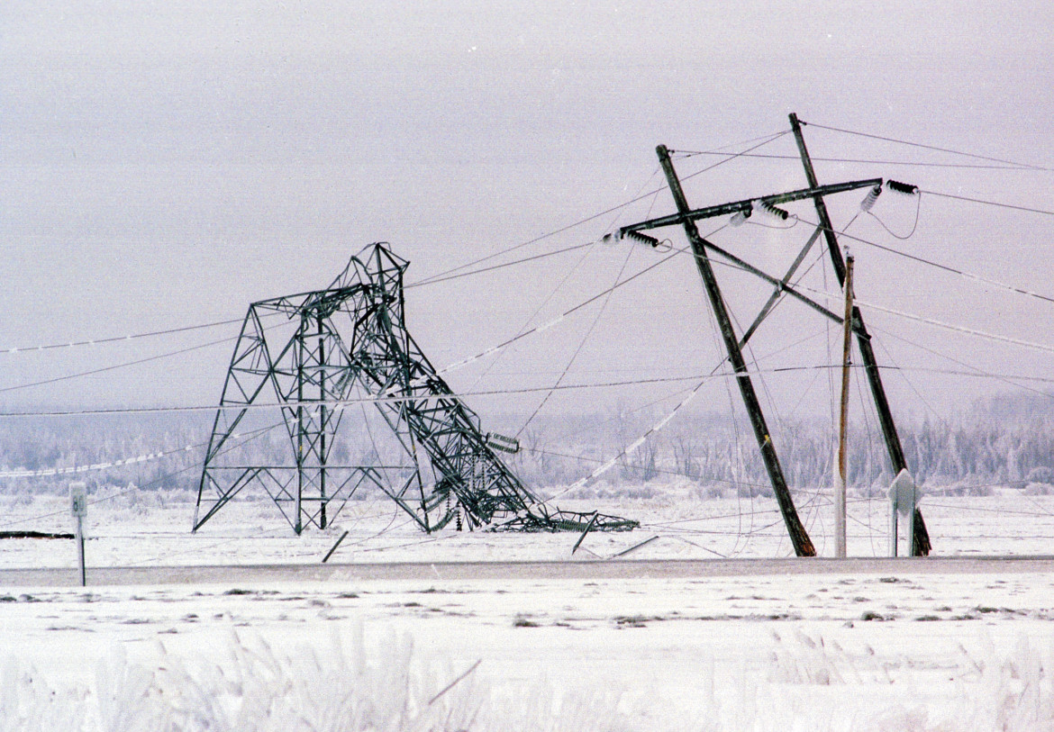
Top 5 Worst Transmission Line Disasters in History
Top 5 Worst Transmission Line Disasters in History Causes, technical failures, cascading effects, and engineering lessons learned This a...
-
Hello. In this blog, we will try to create a steel pole model, using the PLS Pole software of Power Lines System. This created pole will pr...
-
 When a conductor is covered with ice and/or is exposed to wind, the effective conductor weight per unit length increases. During occasions o...
 -
 Yup, you read it right. This is about the World's Longest Overhead Transmission Line as of today. It is around 1700 km in length, trans...
