A transformer, unlike a motor, has no mechanical output (expressed in kW). The current flowing through it can vary in power factor, from zero PF lead (pure capacitive load) to zero PF lag (pure inductive load) and is decided by the load connected to the secondary.
The conductor of the winding is rated for a particular current beyond which it will exceed the temperature for which its insulation is rated irrespective of the load power factor. Similarly, the voltage that can be applied to a transformer primary winding has a limit.
Exceeding this rated value will cause magnetic saturation of the core leading to distorted output with higher iron losses.
It is therefore usual to express the rating of the transformer as a product of the rated voltage and the rated current (VA or kVA). This however does not mean that you can apply a lower voltage and pass a higher current through the transformer.
The VA value is bounded individually by the rated voltage and rated current.
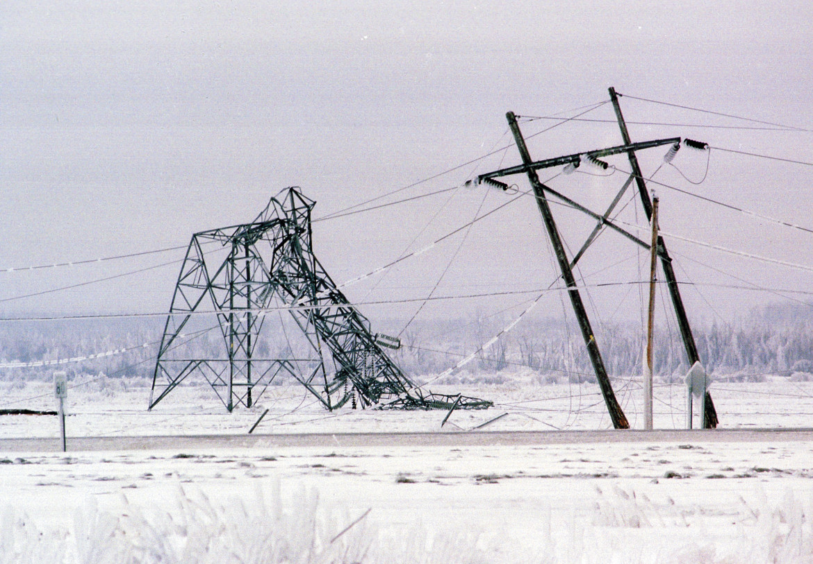
Top 5 Worst Transmission Line Disasters in History
Top 5 Worst Transmission Line Disasters in History Causes, technical failures, cascading effects, and engineering lessons learned This a...
-
Hello. In this blog, we will try to create a steel pole model, using the PLS Pole software of Power Lines System. This created pole will pr...
-
 Yup, you read it right. This is about the World's Longest Overhead Transmission Line as of today. It is around 1700 km in length, trans...
 -
 When a conductor is covered with ice and/or is exposed to wind, the effective conductor weight per unit length increases. During occasions o...

No comments:
Post a Comment