If a short circuit is applied to the terminals of a synchronous generator, the short-circuit current starts out at a high value and decays to a steady-state value some time after the inception of the short circuit.
Since a synchronous generator continues to be driven by its prime mover and to have its field externally excited, the steady-state value of short-circuit current will persist unless interrupted by some switching means.
An equivalent circuit consisting of a constant driving voltage in series with an impedance that varies with time is used to represent this characteristic. The varying impedance consists primarily of reactance.
Xd"= subtransient reactance; determines current during Þrst cycle after fault occurs. In about 0.1 s reactance increases to
Xd'= transient reactance; assumed to determine current after several cycles at 60 Hz. In about 0.5 to 2 s reactance increases to
Xd = synchronous reactance; this is the value that determines the current ßow after a steadystate condition is reached.
Because most short-circuit interrupting devices, such as circuit breakers and fuses, operate well before steady-state conditions are reached, generator synchronous reactance is seldom used in calculating fault currents for application of these devices.
Synchronous generator data available from some manufacturers includes two values for direct axis subtransient reactanceÑfor example, subtransient reactances Xdv"(at rated voltage, saturated, smaller) and Xdi" (at rated current, unsaturated, larger).
Because a shortcircuited generator may be saturated, and for conservatism, the Xdv" value is used for short-circuit current calculations.
 Yup, you read it right. This is about the World's Longest Overhead Transmission Line as of today. It is around 1700 km in length, trans...
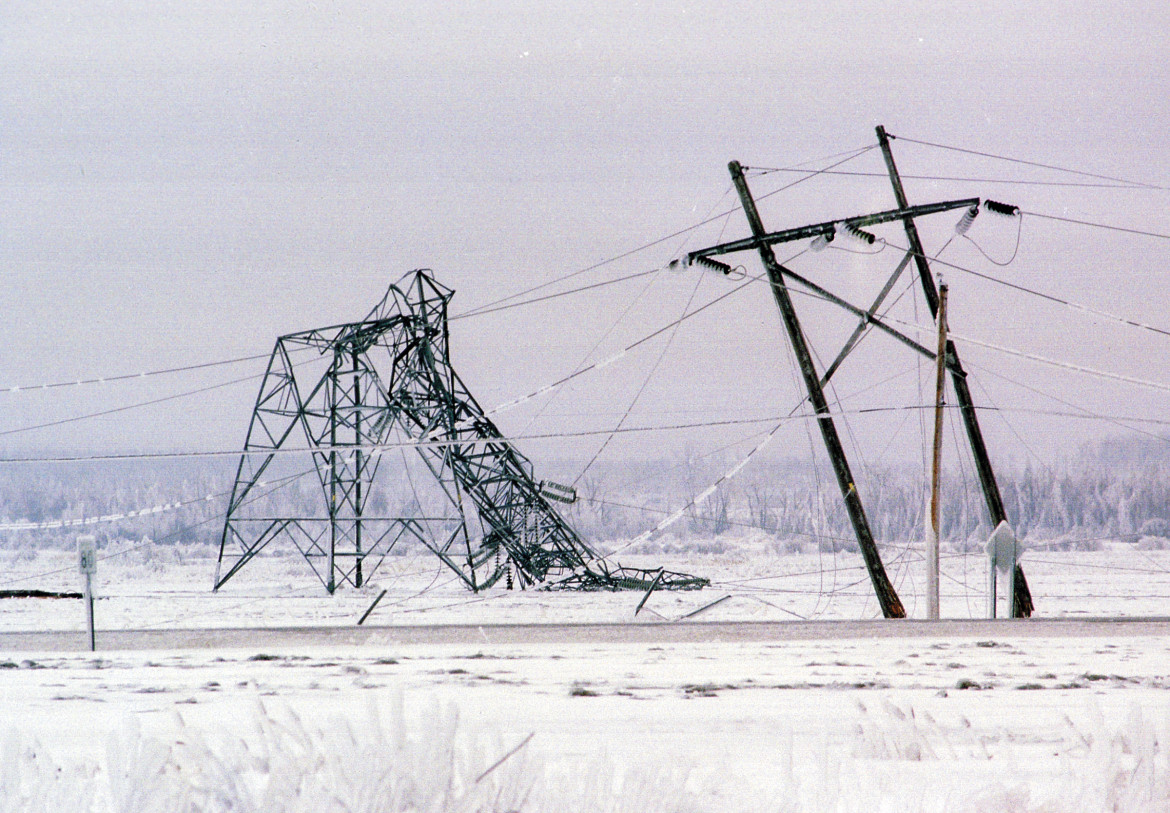
 When a conductor is covered with ice and/or is exposed to wind, the effective conductor weight per unit length increases. During occasions o...
No comments:
Post a Comment