Causes of phase-voltage unbalance
Most utilities use four-wire grounded-wye primary distribution systems so that single-phase distribution transformers can be connected phase-to-neutral to supply single-phase loads, such as residences and street lights. Variations in single-phase loading cause the currents in the three-phase conductors to be different, \ producing different voltage drops and causing the phase voltages to become unbalanced.
Normally the maximum phase-voltage unbalance will occur at the end of the primary distribution system, but the actual amount will depend on how well the single-phase loads are balanced between the phases on the system.
Perfect balance can never be maintained because the loads are continually changing, causing the phase-voltage unbalance to vary continually. Blown fuses on three-phase capacitor banks will also unbalance the load and cause phase-voltage unbalance.
Industrial plants make extensive use of 480Y/277 V utilization voltage to supply lighting loads connected phase-to-neutral. Proper balancing of single-phase loads among the three phases on both branch circuits and feeders is necessary to keep the load unbalance and the corresponding phase-voltage unbalance within reasonable limits.
Measurement of phase-voltage unbalance
The simplest method of expressing the phase-voltage unbalance is to measure the voltages in each of the three phases:
The amount of voltage unbalance is better expressed in symmetrical components as the negative sequence component of the voltage:
percent unbalance = maximum deviation from average/ average X 100%
voltage unbalance factor = negative-sequence voltage/ positive-sequence voltage
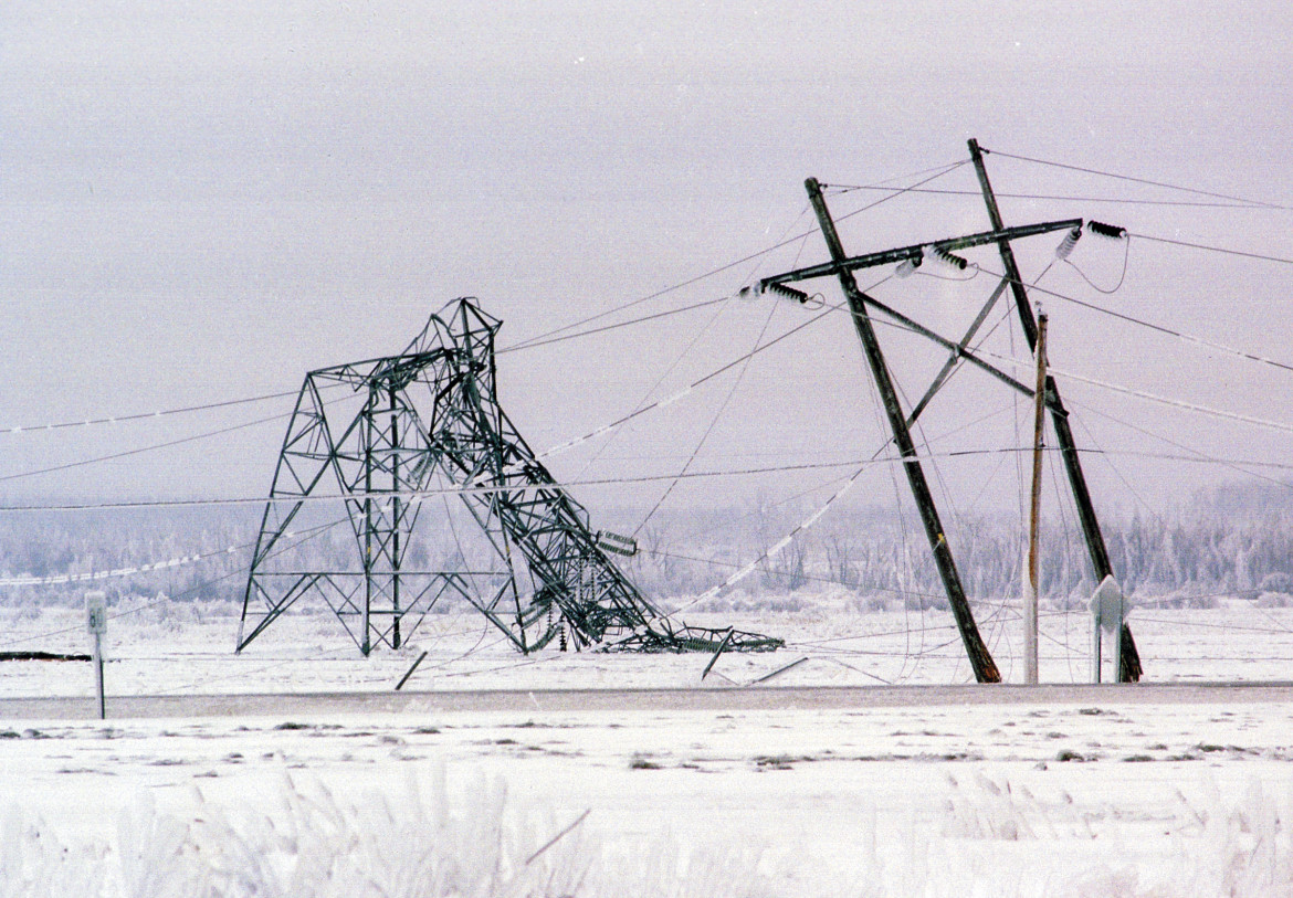
Top 5 Worst Transmission Line Disasters in History
Top 5 Worst Transmission Line Disasters in History Causes, technical failures, cascading effects, and engineering lessons learned This a...
-
Hello. In this blog, we will try to create a steel pole model, using the PLS Pole software of Power Lines System. This created pole will pr...
-
 Yup, you read it right. This is about the World's Longest Overhead Transmission Line as of today. It is around 1700 km in length, trans...
 -
 When a conductor is covered with ice and/or is exposed to wind, the effective conductor weight per unit length increases. During occasions o...

No comments:
Post a Comment