Transmission Lines Design, Electrical Engineering Calculations, Substation Notes, Line Parameters, Relay Protection Tutorials, and Engineering Guides for Students and Professionals.
SEASON'S GREETINGS
Get link
Facebook
X
Pinterest
Email
Other Apps
MERRY CHRISTMAS
TO ALL THE
READERS, SUBSCRIBERS AND FOLLOWERS OF
TRANSMISSION LINES DESIGN AND ELECTRICAL ENGINEERING HUB!!!
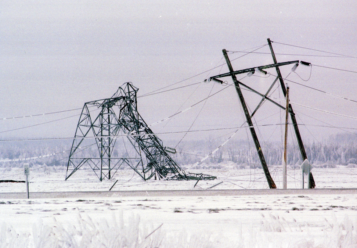
When a conductor is covered with ice and/or is exposed to wind, the effective conductor weight per unit length increases. During occasions of heavy ice and/or wind load, the conductor catenary tension increases dramatically along with the loads on angle and deadend structures. Both the conductor and its supports can fail unless these high-tension conditions are considered in the line design. Certain utilities in very heavy ice areas use glaze ice thickness of as much as 2 in (50 mm) to calculate iced conductor weight. Similarly, utilities in regions where hurricane winds occur may use wind loads as high as 34 lb/ft2 (1620 Pa). As the NESC indicates, the degree of ice and wind loads varies by region. Some areas may have heavy icing, whereas some areas may have extremely high winds. The loads must be accounted for in the line design process to prevent a detrimental effect on the line. Some of the effects of both the individual and combined co...
Yup, you read it right. This is about the World's Longest Overhead Transmission Line as of today. It is around 1700 km in length, transmitting power of 560 MW. Interestingly enough it its transmission voltage is 500 kV dc, mainly due its relatively long distance.
The detailed procedure for insulation co-ordination set out in IEC 60071-1 (European standard EN60071-1 is identical) consists of the selection of a set of standard withstand voltages which characterize the insulation of the equipment of the system. This set of withstands correspond to each of the different stresses to which the system may be subject: • Continuous power frequency voltage (the highest voltage of the system for the life of the system). • Slow-front overvoltage (a standard switching impulse). • Fast-front overvoltage (a standard lightning impulse). • Very-fast-front overvoltage (depends on the characteristics of the connected apparatus). • Longitudinal overvoltage (a voltage between terminals combining a power frequency voltage at one end with a switching (or lightning) impulse at the other). These voltages and overvoltages need to be determined in amplitude, shape and duration by system study. For each class of overvo...
Comments